

Build stuff. Watch it break.
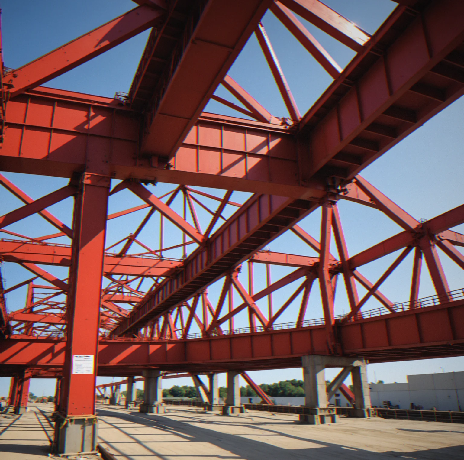
See exactly why it fails under real conditions.
You're designing structures that have to hold up under changing constraints. Sharp angles pile stress into one spot. Thin sections bend and snap. Loads shift when you're not looking. Materials break the way they actually do in the world—fibers tearing at weak points, joints shearing apart, long thin pieces twisting sideways and collapsing. This is engineering with no shortcuts. No soft geometry. No second chances. Everything you build gets tested to failure.
How Sharpbridge Works
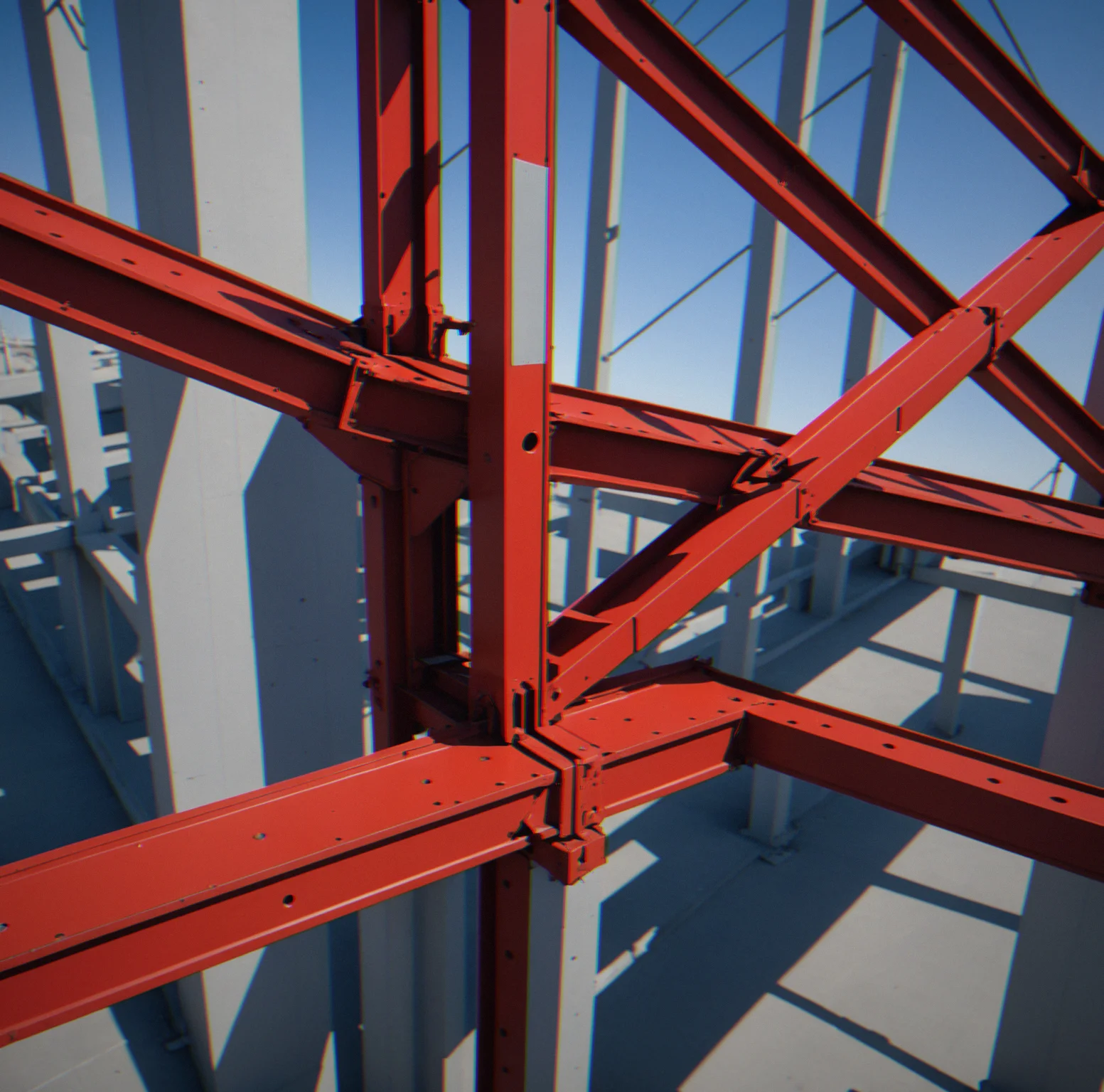
Acute Angles Fail First
A 30-degree joint is basically a stress trap. Your structure won't fail evenly—it'll split right where the angles squeeze hardest. You either design around this or watch it go.
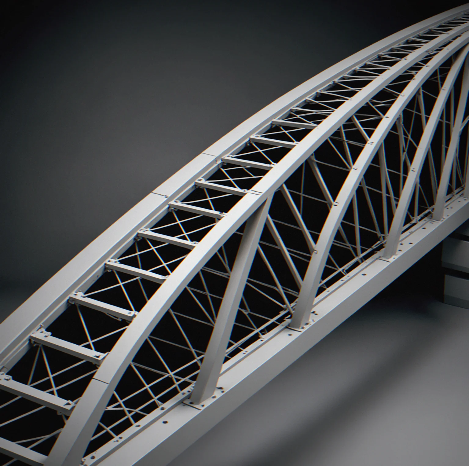
Narrow Spans Buckle
Slender members buckle before they break. Lateral-torsional buckling happens faster than the material actually snapping. In long, thin components, how it's shaped matters way more than what it's made of.

Dynamic Loads Shift in Real Time
Puzzles don't lock the load in one direction. Support points move. Forces rebalance as you go. What works under static conditions can fall apart the moment something changes.
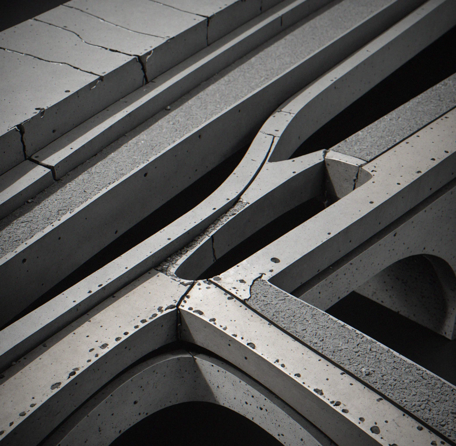
Material Selection Compounds Constraints
Steel bends before it breaks. Concrete snaps. Composites shear in the wrong direction if you're not careful. Each one has its own weight penalty and strength trade-offs. Pick one and then work within what you chose.

Stress Paths Become Visible
Load follows specific routes through your structure. Bad geometry forces stress to bunch up in one spot. When you fix the path, stress spreads out. Ignore it and failure happens locally.
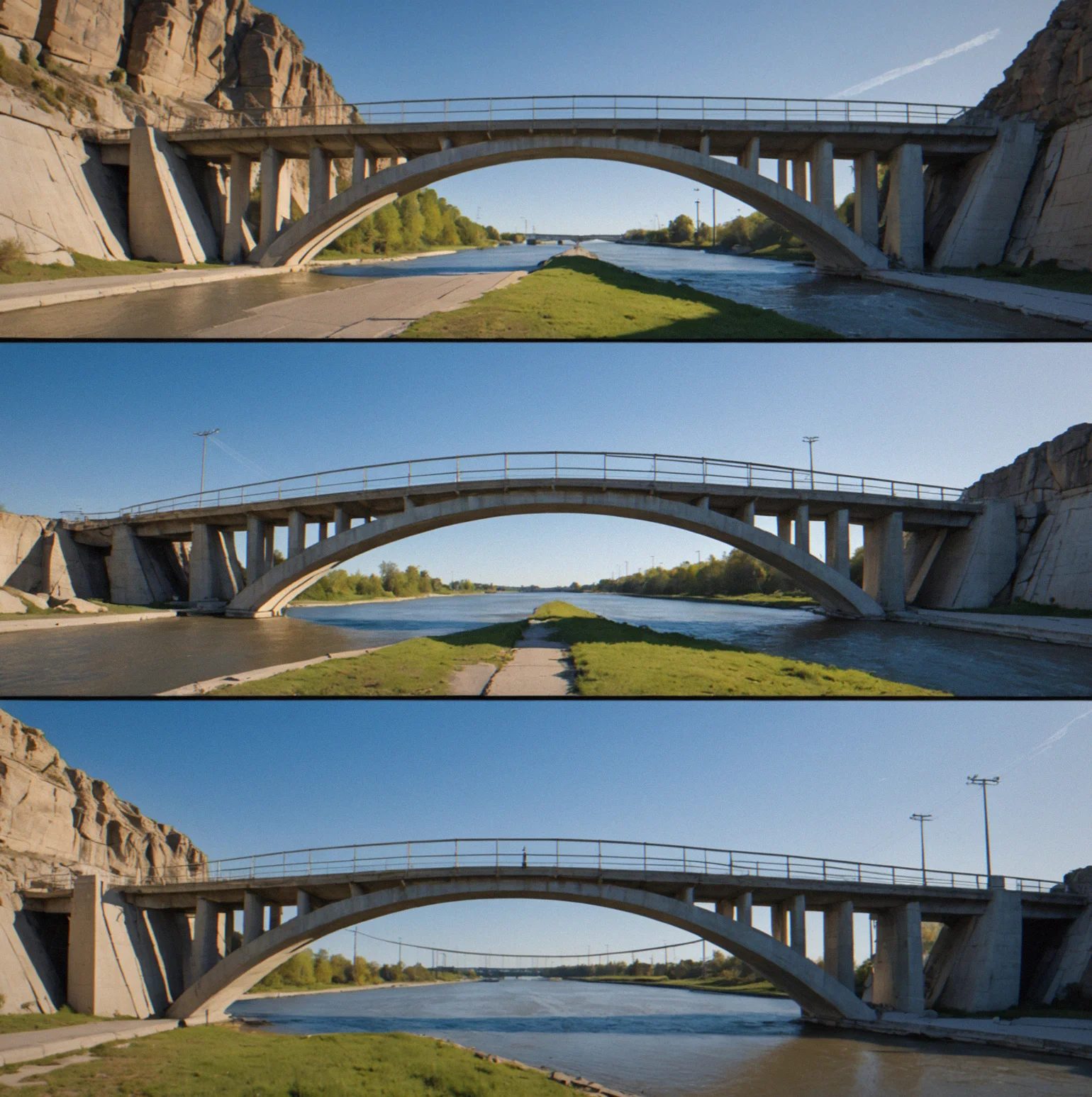
Failure Modes Vary by Design
One joint might fail in tension. Put the same joint in a different structure and it fails in shear instead. Buckling happens sometimes and doesn't happen other times, depending on the proportions. You need to know which failure will hit your design first.
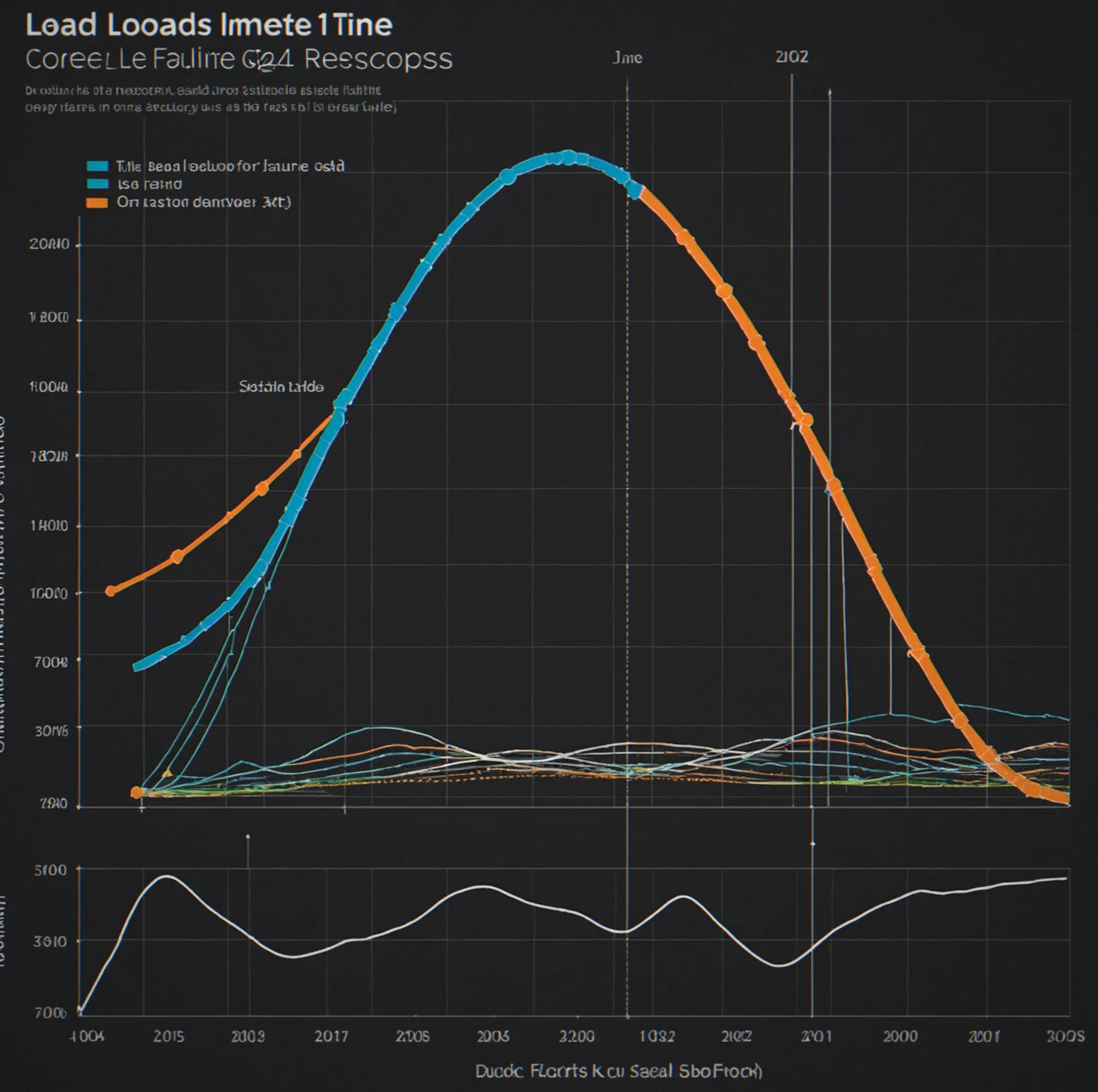
Time Pressure Compounds Difficulty
Load ramps up gradually. Your design either survives the whole sequence or it doesn't. There's no instant collapse moment—you watch failure spread through the structure and can't fix it mid-test.
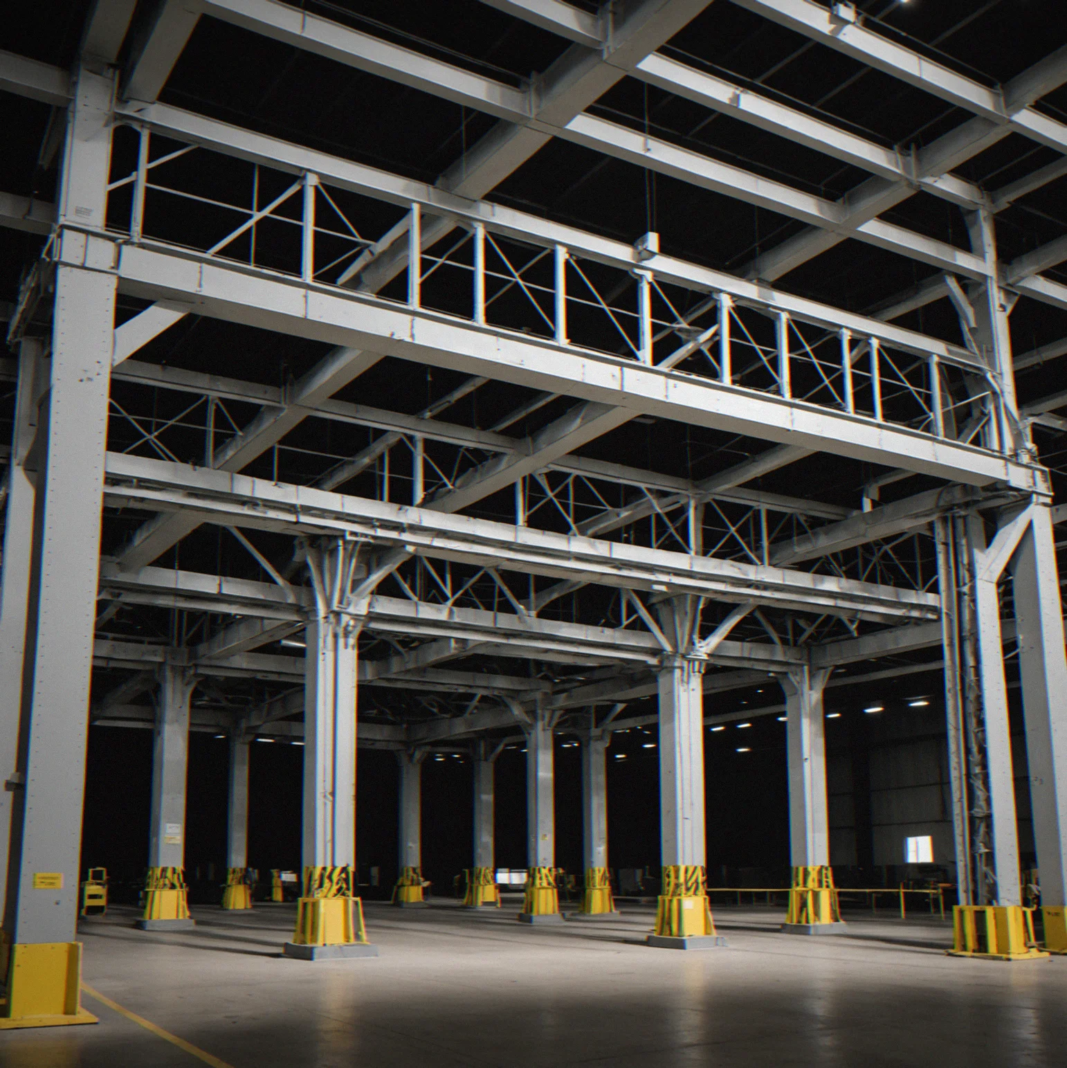
Mass Budget Enforces Optimization
You get fifty kilograms. Use more steel and you're over. Use less and it snaps. Every gram matters. Real optimization instead of tweaking forever.
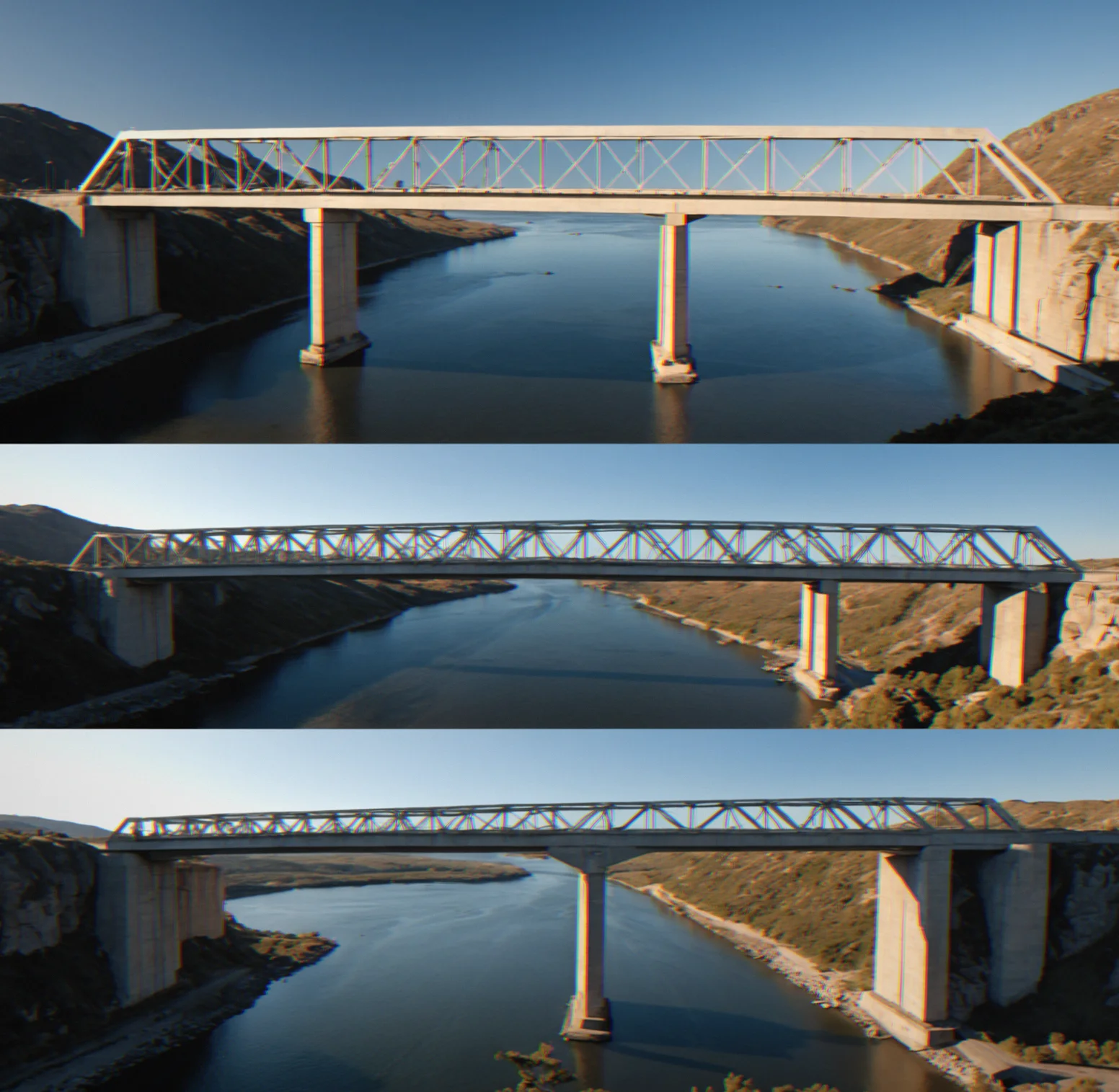
Iteration Loops Run Fast
Build, test, fail, rebuild. Each test takes seconds. That speed means you can try thirty variations in the time traditional FEA software runs once. Quick cycles teach you faster.
Optimization Satisfies Like No Tutorial Can
When your design passes every load case and stays under budget, you actually built something. Not by luck—by figuring it out. The rush comes from beating hard constraints, not from checking off tasks.
Stress Under Load
Real geometry breaks in real ways. These images show what happens when sharp angles, thin spans, and heavy loads push against physics that doesn't give. Just structures failing.

Steel truss joint at 25 degrees with stress concentrated in deep red, yellow showing where secondary stress spikes appear nearby

Cantilever beam bending downward under a point load, tip displacement marked with a measurement line showing the span-to-depth ratio
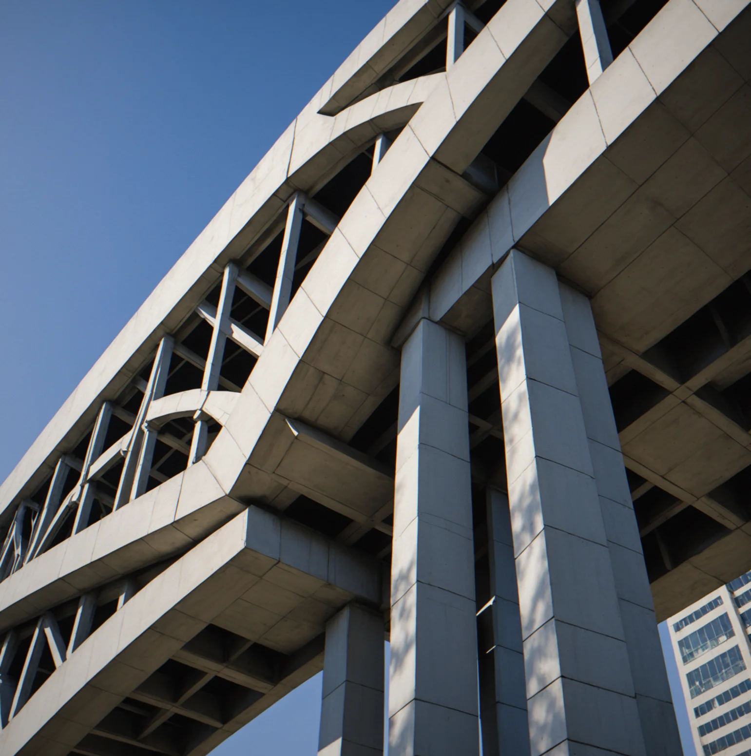
Column buckling into an S-shape, Euler buckling cutve overlaid to show when the critical load gets exceeded
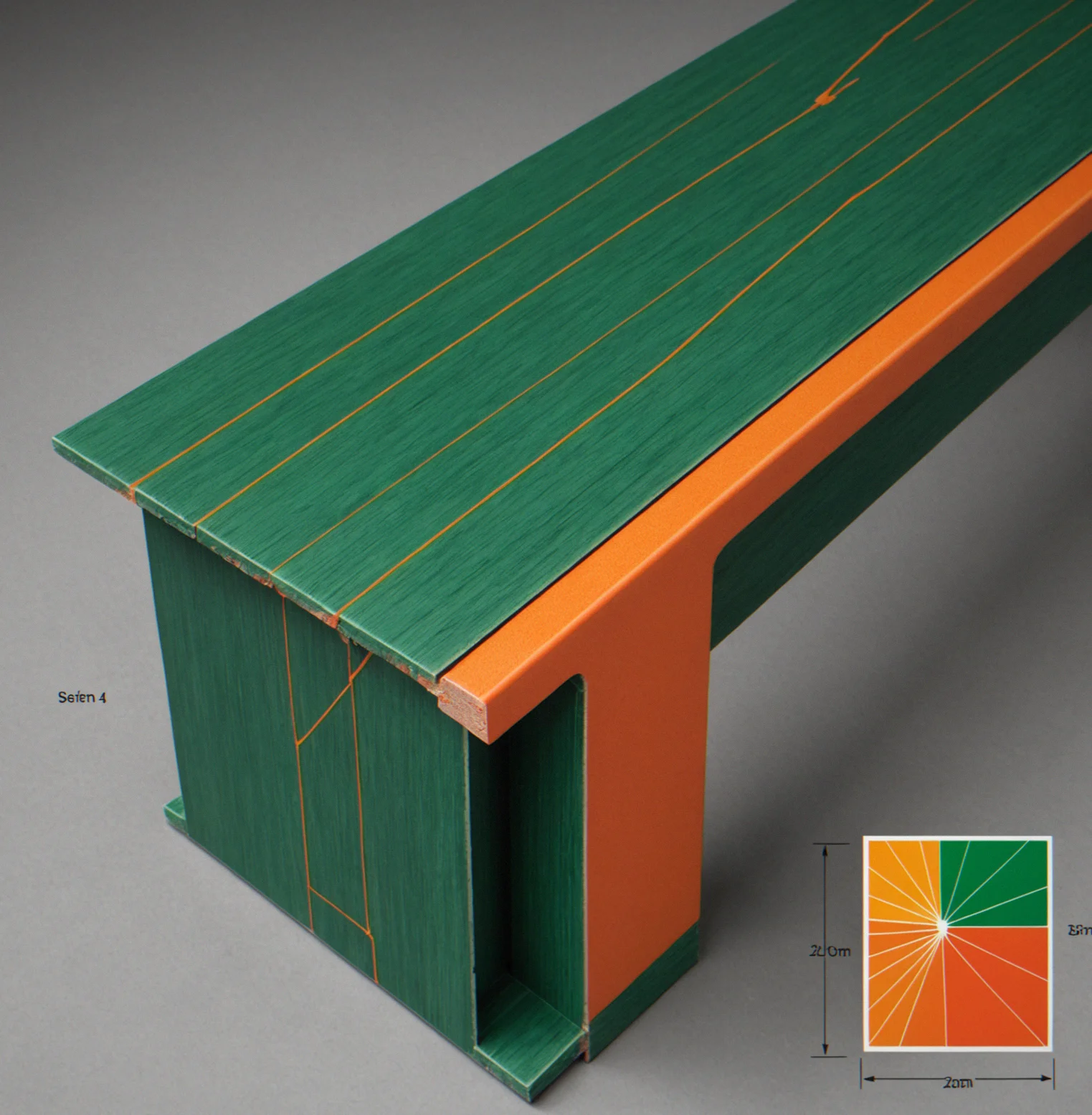
Composite laminate with fiber strength shown in green, transverse shear weakness in orange, and a ply orientation diagram
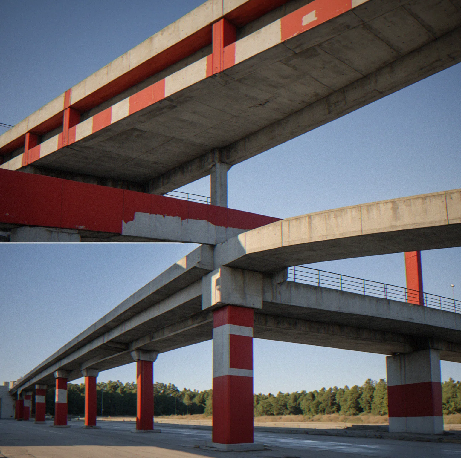
Concrete beam with a tension crack opening from the bottom, tensile stress gradient shifting from white to red
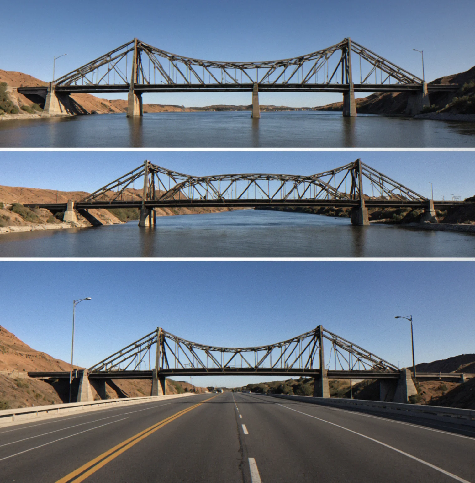
Load sequence showing structure respohse at four stages—25, 50, and 75 percent load, plus failure—displayed side by side
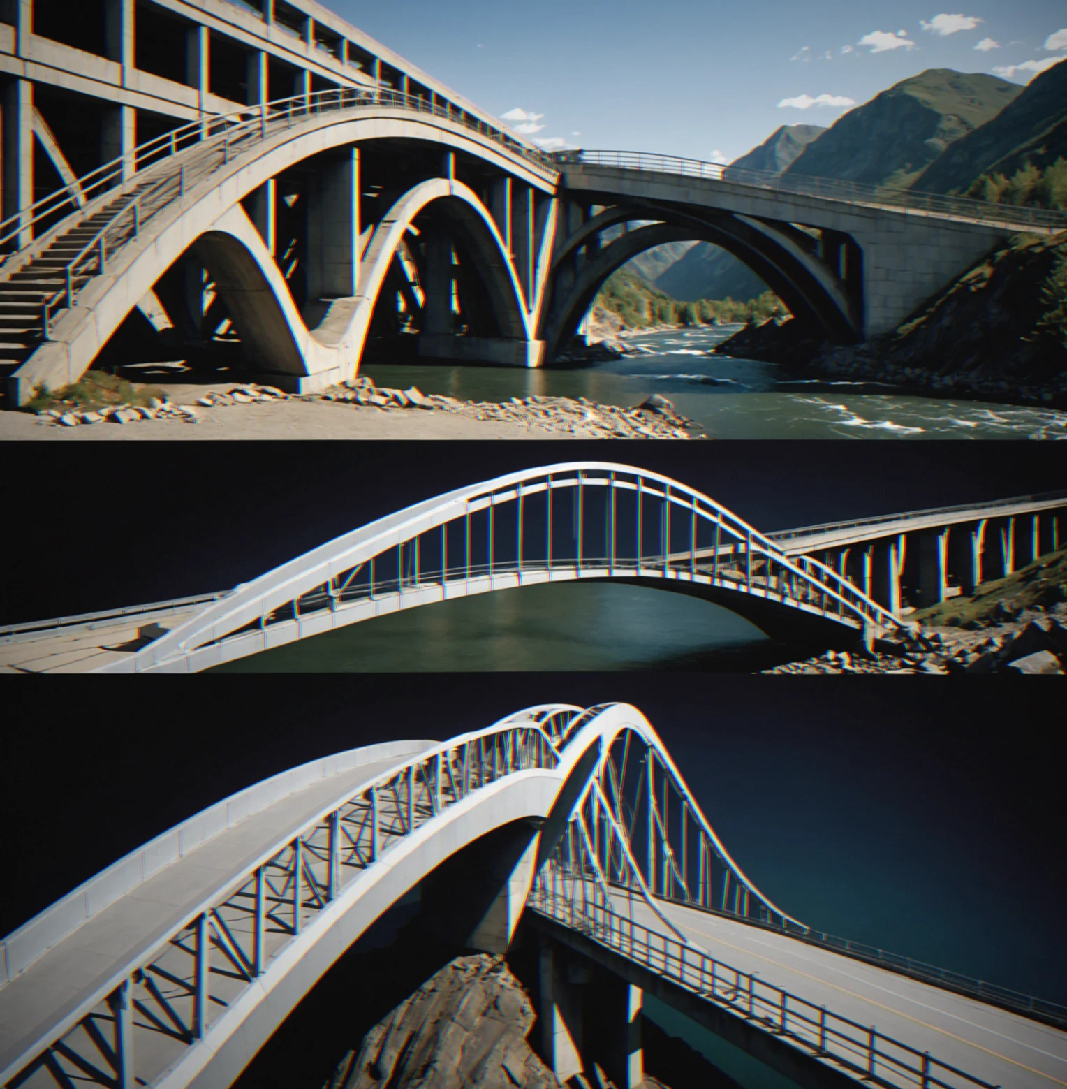
Realistic Material Failure
Steel bends before it snaps. Concrete just cracks under tension without any warning. Composites shear in the direction perpendicular to the fibers. Materials act like they do in real life, not some simplified version that hides what actually happens.
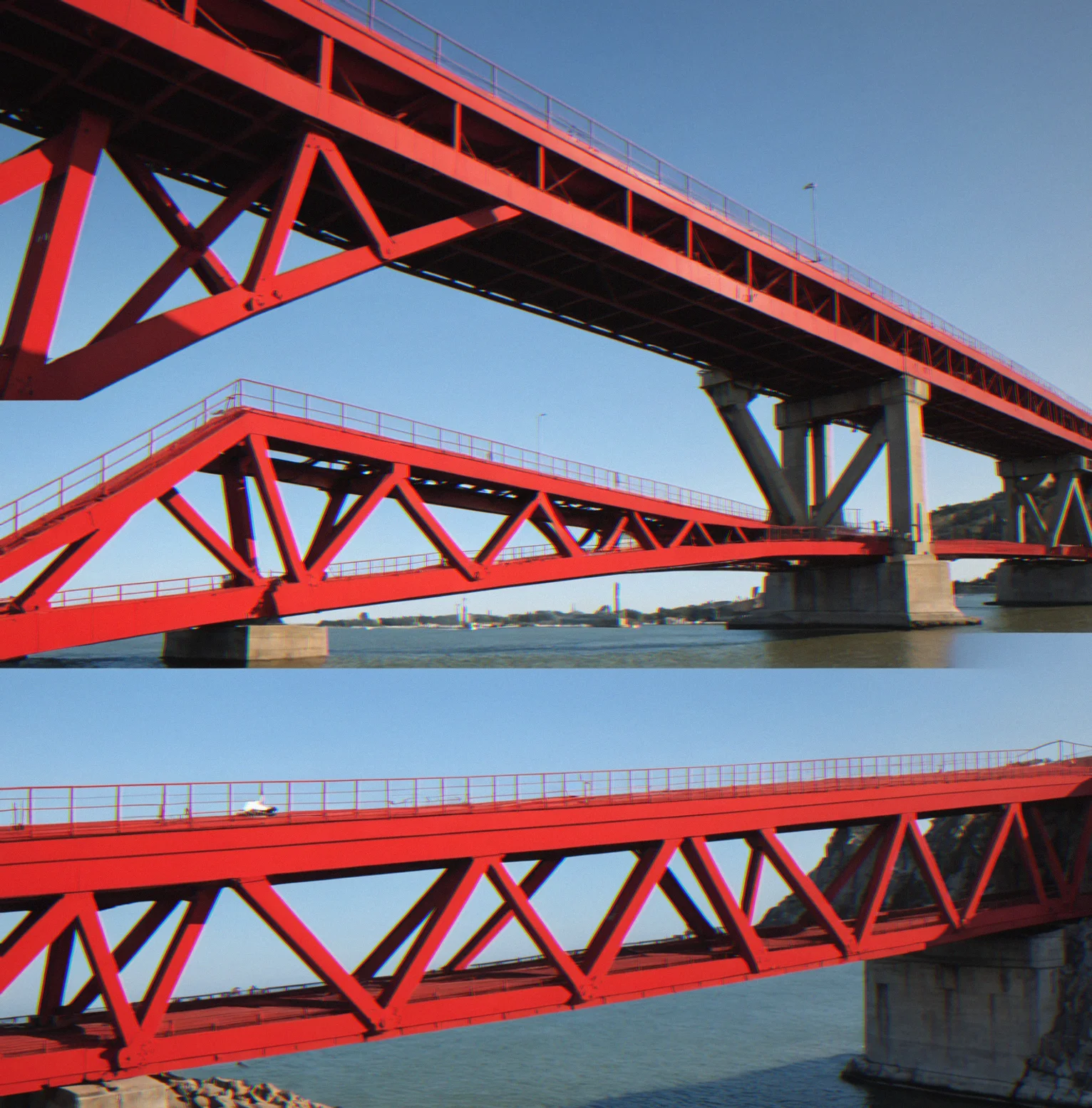
Acute Angles Expose Weakness
A 30-degree joint concentrates shear stress way more than a 45-degree one. Your design doesn't fail evenly, it fails where the stress piles up. That's always at the sharp angles.
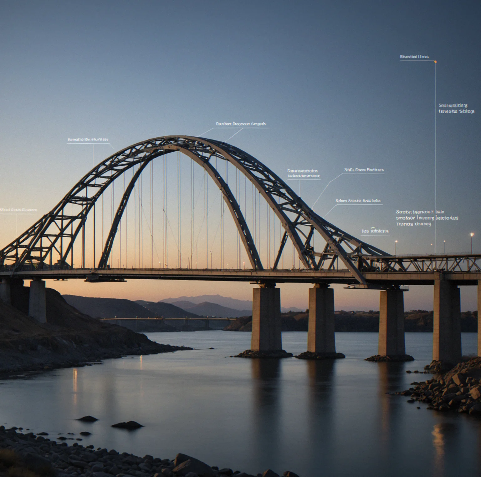
Dynamic Load Shifts
Loads move around. Support points don't stay where you put them. Forces rebalance as things happen. What works fine when nothing changes can fall apart the moment something does, and you can't fix it mid-test.

Narrow Spans Buckle First
Long skinny pieces give out before they even start stretching. Lateral-torsional buckling kicks in at way lower loads than the material's strength suggests, which catches most people off guard. Geometry beats material strength when you're dealing with long thin components.
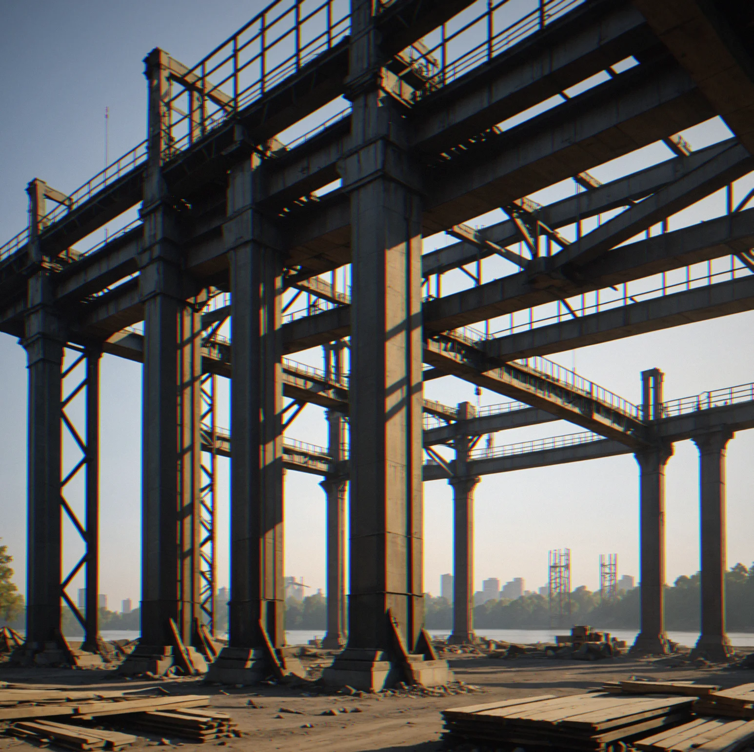
Optimization Under Brutal Constraints
You get 40 kilograms and three different load scenarios. Every member you pick affects everything else. Adding material increases weight and strength at the same time. The real payoff is working within these limits, not having unlimited resources to throw at it.
Stress Concentration at Acute Angles
That 25-degree joint? It's going to concentrate stress somewhere in the range of 3 to 4 times higher than what you'd see at a 45-degree corner. Geometry has a way of amplifying loads right where you don't want them. You either design around it or accept that failure's coming to that spot first.
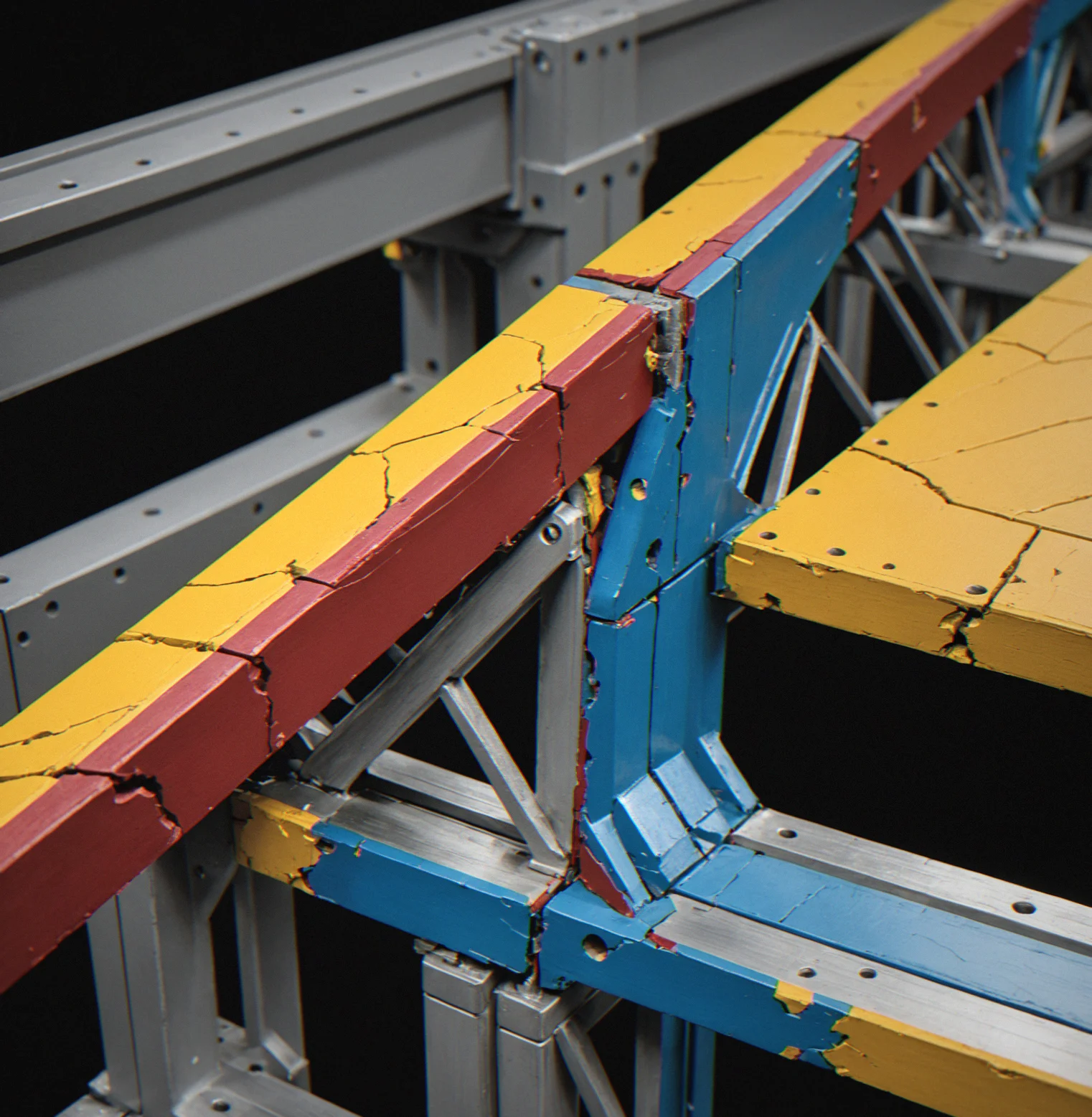
Buckling Before Yield
Long, thin beams don't care about their material's yield strength—they buckle first. Euler's critical load is what actually matters. In narrow spans, slenderness wins over raw strength every time.

Material-Specific Failure Modes
Steel bends and yields gradually. concrete just snaps. Composites fail in whatever direction their fibers aren't pointing. Every material has its own way of coming apart. Pick your material first, then build your design around how it actually breaks.
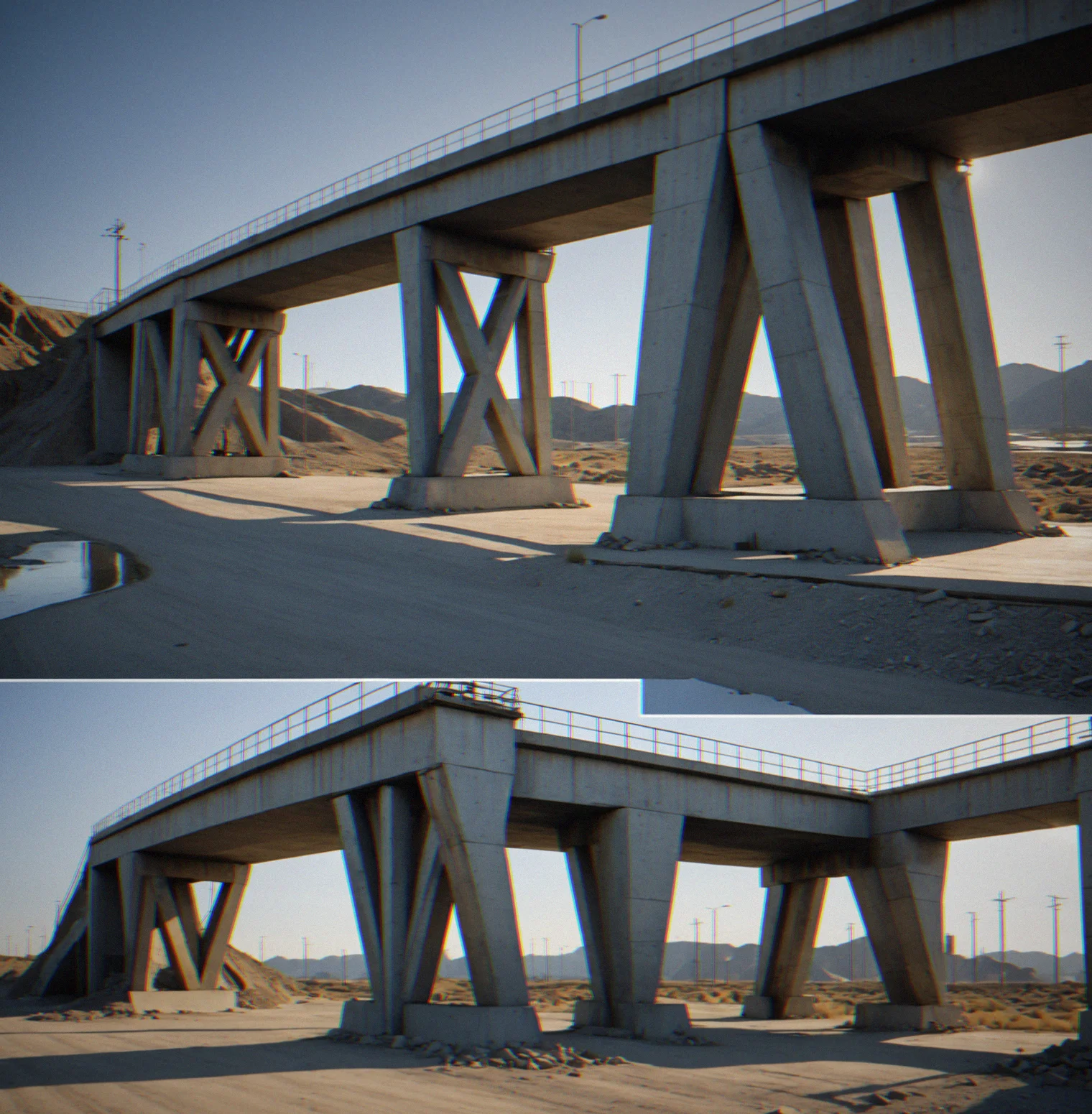
Dynamic Load Migration
Loads shift. Done.
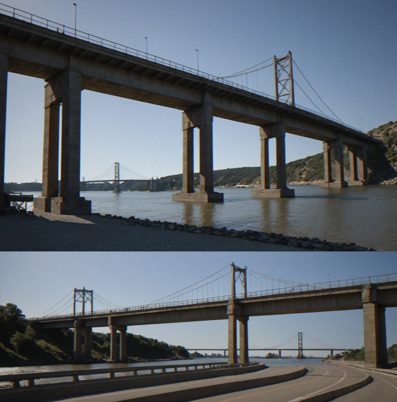
Real Load Paths Visible
Force takes specific routes through your structure based on how you've shaped it. Bad geometry means those paths get tangled up and stress piles on in isolated spots. Get the path right and stress distributes smoothly. Get it wrong and failure happens right away.

Brutal Material Budget
You've got 35 kilograms to work with. Every gram you add strengthens things but also weighs more. Go over and you're out. Go under and something fails under load. There's no way around it—you have to optimize.
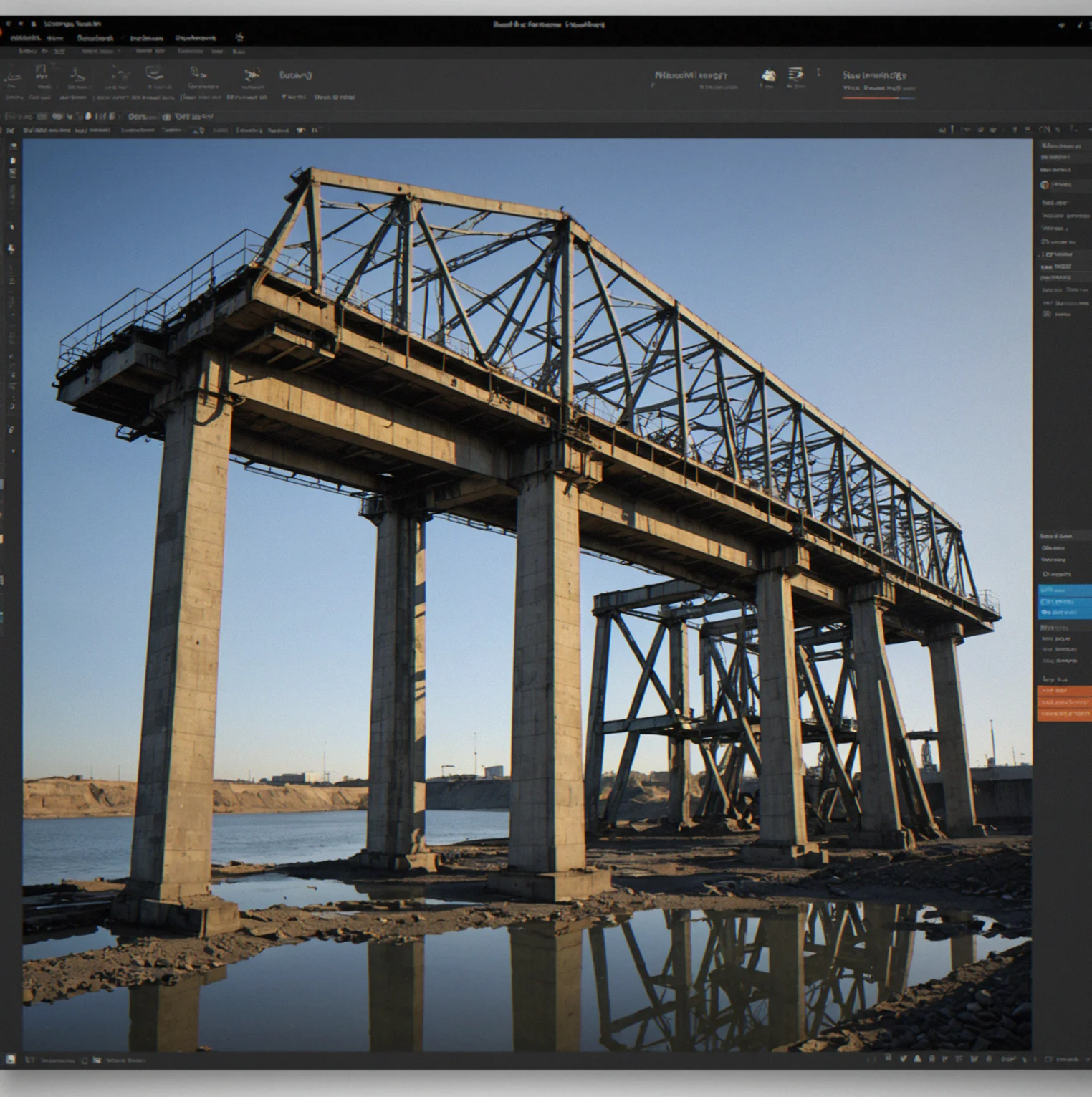
Failure Propagation in Real Time
As load climbs, your structure doesn't blow apart all at once. It fails in stages. You watch cracks spread. You watch members bend past their limit. You watch joints start to separate. You see exactly which thing breaks first and which comes next.
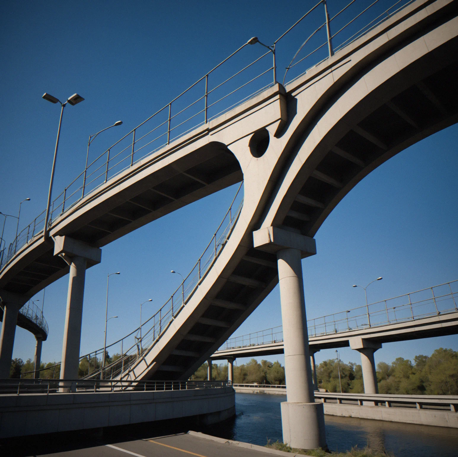
When Things Break
Stress piles up where geometry gets sharp and spans get long. Watch what happens when acute angles, tight sections, and shifting loads find the weak spot. Raw footage, no interpretation.
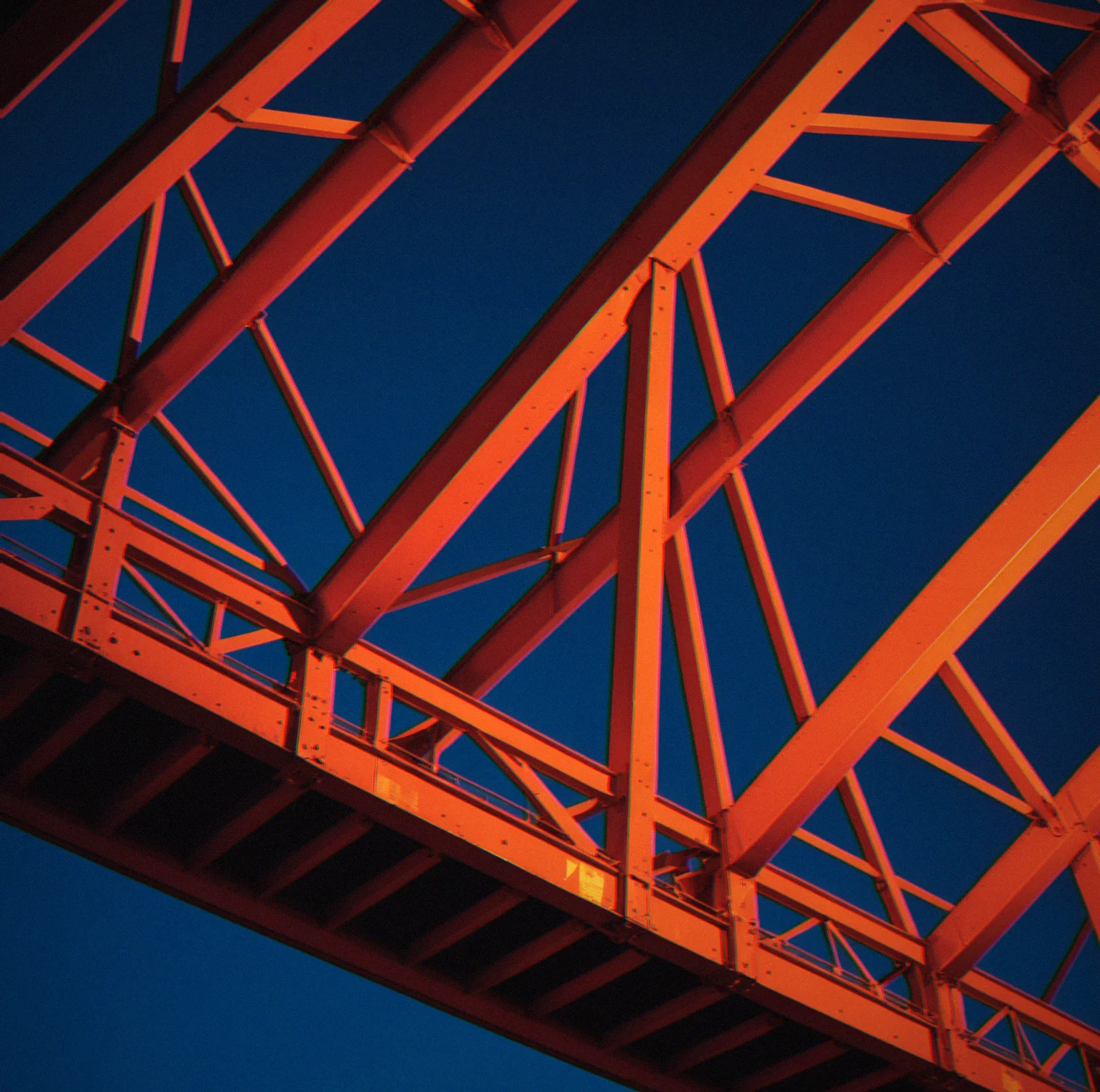
Steel truss joint bent at a tight angle under straight-line load. The sharp corner glows red where stress peaks, fading to orange as it spreads outward
Tall thin column twisted sideways in a smooth curve, arrows showing how it's bending out to the side instead of straight down
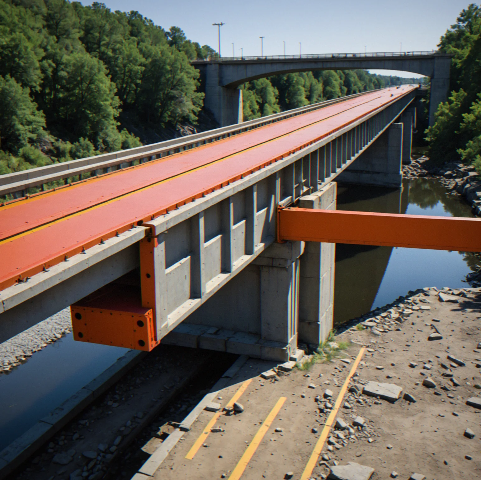
Beam stuck at one end and loaded across its length. Red shows where the bending stress mxaes out near the fixed end, orange marks the shear zones nearby
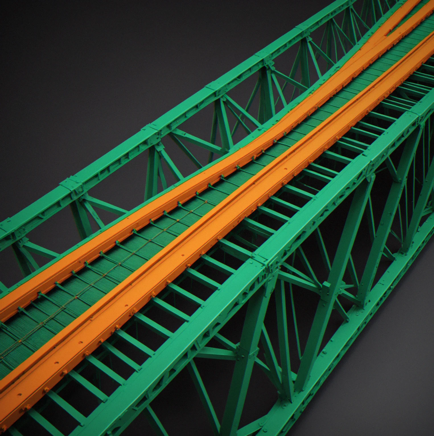
Layered composite material with fibers running one direction in green, matrix starting to fail in orange, showing how strength changes based on direction

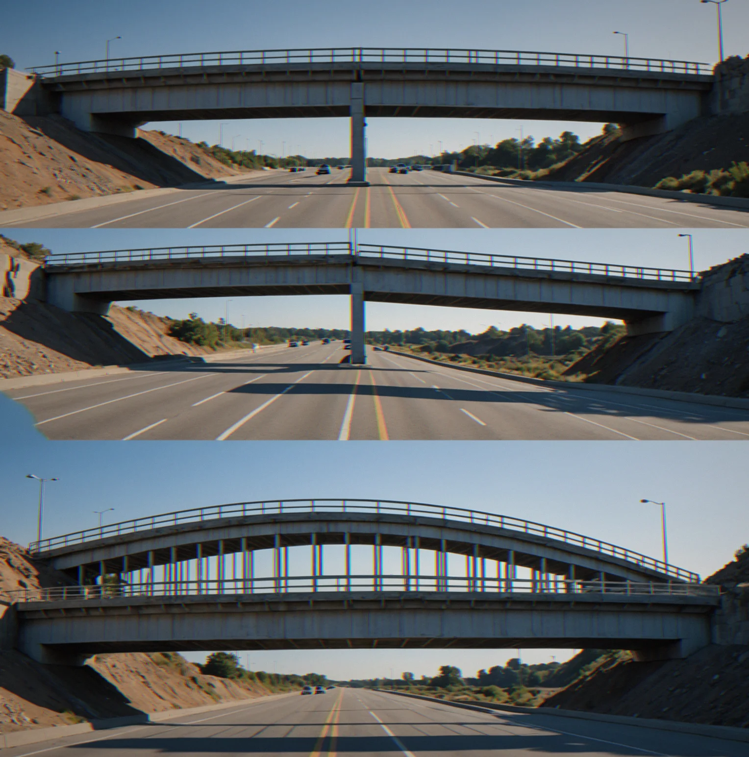
Load applied step by step at 0, one-third, two-thirds, and full capacity. Shape warps more at each stage, stress field gets brighter as failure approaches
TOTAL SAMPLES
5
STRESS ZONES
VARIABLE
FAILURE MODES
MULTI
Core Mechanics
Why Structures Fail
What separates something that actually hollds together from something that just crumbles? It all comes down to geometry. A joint at 30 degrees concentrates shear stress way more intensely—we're talking 3.5 times higher—than one at 50 degrees. Then there's the slender beam problem. It'll buckle at stress levels that are nowhere near what the material itself could theoretically handle. Where failure happens depends entirely on load paths, and those routes through your structure aren't evenly distributed. They concentrate at specific weak spots you've created through your design choices. This isn't just abstract stuff to think about. It's the difference between solving a puzzle and watching the whole thing catastrophically fail the moment you actually apply a load.
Why does any of this matter in a game context? Because working within constraints teaches you something real about how engineering actually works. You can't just throw more material at acute angles and expect them to behave. You can't solve buckling by making things thicker. Dynamic loads shift around, which forces you to design for multiple situations at once. The real payoff comes from figuring out how to beat these harsh parameters, not from having unlimited resources to throw at problems. That's how structures get designed in the actual world.
Stress Concentration
Tight angles create local stress spikes that are exponentially worse. A 25-degree joint can peak at four times the stress of the surrounding material.
Buckling Governs Slender Members
Long, thin components give out before the material itself reaches its breaking point. Euler's critical load is what kills them, not the material's yield strength.
Load Paths Define Failure Location
Force flows through your structure based on how you've shaped it. Inefficient paths concentrate stress in specific spots rather than spreading it out.
Material Behavior Varies by Type
Steel bends and yields gradually. Concrete shatters without warning. Composites fail in particular directions. You pick your material, then design around how it actually behaves.
Technical Analysis
Questions
Common Concerns
You'll hear the same questions over and over. Here's what matters before you start.
Get monthly puzzle updates and breakdowns of what breaks them.
We drop new scenarios every month. Each one comes with a breakdown of how it works, what can go wrong, which constraints actually matter and the physics behind it. Straight analysis and design problems. No marketing.
After Submit
Done. Look for a confirmation email. The first breakdown will be there next week.